
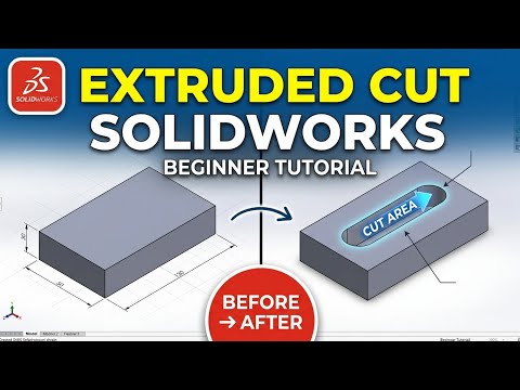
Are you ready to unlock the full potential of parametric modeling? Whether you are an aspiring engineer, product designer, or hobbyist, mastering the fundamental tools of 3D CAD software is your gateway to turning digital concepts into real-world objects. Among the most essential features in SOLIDWORKS is the Extruded Cut tool.
In this beginner-friendly guide, we break down how to use the Extruded Cut feature step-by-step so you can start creating precise holes, slots, and complex cutouts in your models with ease.
What is the Extruded Cut Feature?
In SOLIDWORKS, the Extruded Cut tool works as the exact counterpart to the Extruded Boss/Base feature. While an extruded boss adds material to build a 3D shape, an extruded cut removes material from an existing solid body. It is one of the most frequently used functions in 3D CAD modeling, vital for designing everything from simple screw holes to intricate mechanical assemblies.
Step-by-Step Guide: How to Perform an Extruded Cut
- Select Your Plane or Face: Click on the flat surface of an existing solid body or select a standard reference plane where you want to make your cut.
- Create a 2D Sketch: Start a new sketch and draw the closed 2D shape you wish to cut out—such as a circle, rectangle, or custom polygon.
- Activate the Tool: Navigate to the Features tab on the CommandManager and select Extruded Cut.
- Choose Your Direction and End Condition: In the PropertyManager panel, define how deep the cut should go:
- Blind: Enter a specific depth measurement.
- Through All: Cuts completely through the entire solid body.
- Up To Next: Cuts material up to the very next surface it encounters.
- Apply the Cut: Click the green checkmark to finalize the operation. Your 3D model will instantly update with the newly cut geometry.
Pro Tips for Efficient Modeling
- Fully Define Your Sketch: Always add dimensions and geometric relations to your 2D profile before cutting. This ensures your model remains predictable and easy to edit later.
- Use Smart End Conditions: Instead of typing a fixed numerical depth, using options like "Through All" or "Up To Surface" ensures that your cut automatically adjusts if you change the thickness of the base part later.
By mastering these fundamental techniques, you will dramatically speed up your 3D CAD design workflow and gain the confidence to tackles more advanced modeling challenges. Give it a try in your next SOLIDWORKS project!
