Cad 3D Category

Showing posts with label CAD Design. Show all posts

Mastering Precision Design: How to Create a Crown Wireframe Structure in Inventor 3D

Saturday, September 19, 2026
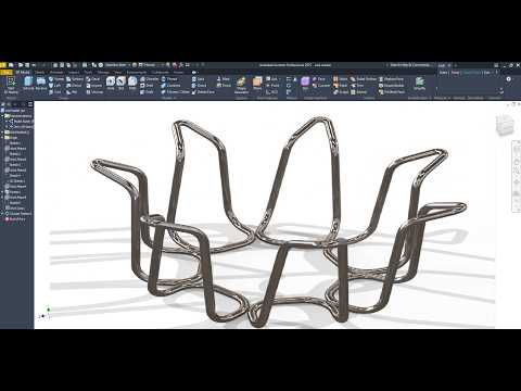
When it comes to high-level mechanical design and intricate geometric modeling, Autodesk Inventor remains a top-tier choice for engineers and designers worldwide. In this guide, we dive into Exercise 227, focusing on the creation of a sophisticated crown-shaped wireframe structure. This particular exercise is designed to test your precision and help you master complex sketching techniques within the software environment.

The Power of Wireframe Modeling

Wireframe structures are the backbone of many advanced industrial designs. Unlike solid modeling, a wireframe focuses on the skeleton of the object, defining the edges and vertices that form its volume. Creating a crown-shaped structure requires a deep understanding of 3D sketching and constraints. By using Inventor 3D, designers can create a series of interconnected paths that represent the delicate yet strong curves of a crown, ensuring that every angle is mathematically accurate.

Key Steps in the Design Process

To begin the crown wireframe, you start with a foundational 2D sketch to establish the base diameter. However, the true magic happens when you transition into the 3D sketching environment. Here, you will use splines and geometric constraints to pull the structure upward, forming the iconic peaks and valleys of a crown.

Precision is the name of the game in this exercise. Using Inventor 3D, you can leverage the "Circular Pattern" tool to ensure that the ornamental ribs of the crown are perfectly symmetrical around the center axis. This not only saves time but guarantees that the structural integrity of the design is maintained throughout the modeling process.

Refining for Professional Results

Once the basic wireframe is established, the next step involves refining the paths. In professional workflows, these wireframes often serve as the path for "Sweep" or "Pipe" commands to create physical wire components. Exercise 227 emphasizes the importance of smooth transitions between segments. By mastering these techniques, you enhance your ability to tackle complex architectural and mechanical projects that require more than just basic primitive shapes.

Whether you are a student or a seasoned professional, practicing these intricate designs in Inventor 3D is an excellent way to sharpen your spatial reasoning and technical skills. This exercise proves that even the most complex aesthetic shapes can be broken down into manageable, logical steps using the right CAD tools.

Continue Reading | ความคิดเห็น

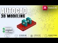
Mastering 3D CAD: How to Model a Mechanical Mounting Bracket in AutoCAD

Friday, September 11, 2026

In the evolving world of mechanical engineering, the ability to transform a 2D concept into a functional 3D model is an essential skill. One of the best ways to sharpen these skills is through practical, hands-on exercises that replicate real-world components. In this guide, we explore the process of creating a mechanical mounting bracket, a fundamental tool in the world of 3D CAD.

Starting with the Foundation: The Base Plate

Every great mechanical model begins with a solid foundation. For this mounting bracket project, we start by constructing a rectangular base plate. In AutoCAD, this involves using primitive shapes or extruding a 2D rectangle to a specific thickness. By assigning a distinct color—such as a vibrant red—designers can easily differentiate between various components within a complex assembly. This level of visual clarity is one of the many advantages of using professional 3D CAD software for mechanical practice.

Precision Engineering and Mounting Holes

A mounting bracket is only as functional as its connectivity. The next critical step in the modeling process is the addition of four precise mounting holes located at the corners of the base. This requires careful measurement and the use of the "Subtract" command to create clean, accurate voids. This stage of the project emphasizes the importance of geometric constraints and precision, ensuring that the digital part would theoretically fit perfectly into a real-world mechanical assembly.

Why Practice Work is Essential

Whether you are a student or an aspiring engineer, consistent practice is the key to proficiency. Transitioning from basic shapes to complex mechanical parts helps users understand the workspace, the Z-axis, and the various shortcuts that speed up the design process. Utilizing 3D CAD for these practice sessions allows you to experiment with different materials, lighting, and viewing angles before moving on to more intricate industrial designs.

Conclusion

Modeling a mechanical mounting bracket is more than just a basic exercise; it is a stepping stone to mastering industrial design. By following these fundamental principles in AutoCAD, you can build a strong portfolio of mechanical parts and gain the confidence needed to tackle large-scale engineering projects. Keep practicing, keep designing, and unlock the full potential of your technical creativity!

Continue Reading | ความคิดเห็น

Mastering 3D CAD: How to Eliminate Tolerances Between Your Design and the Final Print

Wednesday, September 9, 2026

In the world of professional engineering and product design, precision is not just a goal—it is a requirement. However, many designers face a common frustration: a model that looks perfect in its 3D CAD environment often encounters significant dimensional errors once it passes through a slicer and reaches the 3D printer. Bridging this gap between the digital "ideal" and the physical "reality" is the key to professional-grade manufacturing.

The Digital Discrepancy: Why CAD and Slicers Conflict

The journey from a 3D CAD file to a physical object involves several layers of translation. While your design software works with precise mathematical curves and coordinates, a slicer must convert that data into a mesh (usually STL) and then into G-code toolpaths. During this conversion, small rounding errors, mesh density issues, and material shrinkage factors can lead to "tolerances" that ruin a press-fit part or a mechanical assembly.

To solve these discrepancies, professionals must look beyond the default settings. Understanding how your slicer interprets the wall thickness and hole diameters defined in your original design is the first step toward calibration.

Optimizing Your Workflow for Professional Projects

To ensure your project maintains its integrity, you must account for "Horizontal Expansion" and "Hole Expansion" within your slicing software. These settings allow you to compensate for the natural outward flow of plastic. However, the most effective way to minimize error is to design with the manufacturing process in mind. By applying a global tolerance standard (such as 0.1mm to 0.2mm) directly within your 3D CAD workspace, you create a buffer that accommodates the physical limitations of FDM or resin printing.

Scaling Up with Professional Services

Sometimes, high-stakes professional projects require more precision than a desktop setup can provide. This is where professional fabrication services like PCBWay become invaluable. Whether you are integrating a custom PCB into a 3D-printed enclosure or requiring industrial-grade SLS printing, outsourcing to a specialized facility ensures that the tight tolerances you’ve calculated in your design are mirrored in the final product.

Conclusion

Solving the variance between design and production is what separates hobbyist prints from professional prototypes. By mastering your 3D CAD tools and understanding the logic of your slicing software, you can significantly reduce waste and ensure that every part fits perfectly the first time. Precision begins at the design stage—make sure your workflow is ready for the challenge.

Continue Reading | ความคิดเห็น

Precision Design: How to Clean Up Extra Lines in AutoCAD and 3D CAD Projects

Friday, September 4, 2026

Precision is the name of the game when it comes to technical drafting. Whether you are working on a simple 2D floor plan or a complex 3D CAD model, stray lines can clutter your workspace and lead to costly errors. Learning how to efficiently remove these unwanted elements is a fundamental skill that separates amateur hobbyists from professional designers.

Why Line Management Matters

Keeping your drawing "clean" isn't just about aesthetics; it is about data integrity. In the world of professional engineering, extra lines can interfere with object snapping, bloat your file sizes, and cause significant confusion during the rendering phase. If you plan to export your 2D geometry into a more robust 3D CAD environment for extrusion or assembly, those tiny overlapping lines can prevent surfaces from closing properly, resulting in broken geometry that is difficult to fix later.

Essential Commands: Erase and Trim

The most straightforward way to remove an object is the ERASE command (shortcut: E). Simply select the line and hit enter. However, you often don't want to delete an entire entity, but rather a segment that extends too far beyond an intersection. This is where the TRIM command (shortcut: TR) becomes your most valuable tool.

In modern versions of AutoCAD, the Trim tool features a "Quick Mode" by default. This allows you to simply click or "fence" across any line segment to remove it instantly without needing to manually select cutting edges first. For those working on intricate 3D CAD layouts, holding the Shift key while using the Trim command allows you to instantly toggle to the EXTEND command, making it a versatile workflow for cleaning up messy intersections on the fly.

Using the Overkill Command for a Perfect Finish

Sometimes, extra lines aren't visible because they are hidden directly on top of each other. These "duplicate" lines are a common headache in drafting. To solve this, use the OVERKILL command. This powerful tool searches your entire workspace and automatically deletes overlapping or redundant geometry.

By mastering these simple deletion and trimming techniques, you ensure that your projects remain lightweight, professional, and ready for any advanced design stage. Whether you are a student or a seasoned pro, a clean drawing is the foundation of a successful project.

Continue Reading | ความคิดเห็น

2D to 3D Made Easy: Mastering the AutoCAD PRESSPULL Command for 3D CAD

In the fast-paced world of digital design, the ability to transition quickly from a flat sketch to a complex model is a vital skill. If you are looking to excel in 3D CAD, understanding the tools that bridge the gap between 2D drafting and 3D visualization is essential. One of the most powerful and time-saving features available to designers today is the AutoCAD PRESSPULL command.

What Makes PRESSPULL So Powerful?

While many beginners rely solely on the "Extrude" command, the PRESSPULL tool offers a much more dynamic and versatile approach. It allows you to select a bounded area—even if it is not a closed polyline—and instantly pull it into the third dimension. This versatility makes it a cornerstone for anyone looking to streamline their workflow in 3D CAD.

Beyond just adding volume, PRESSPULL is dual-purpose. It can be used to subtract material by pushing a shape into an existing solid, making it an incredibly efficient tool for creating holes, slots, or recessed features without needing complex Boolean operations.

Step-by-Step: From 2D to 3D in Seconds

Mastering this command is straightforward. Follow these steps to speed up your modeling process: 1. Initialize the Command: Type PRESSPULL in the command line or select the icon from the Modeling tab. 2. Select the Area: Hover your cursor over the 2D shape or a bounded internal area. AutoCAD will automatically highlight the detected space. 3. Define the Height: Click and drag your mouse upward to add height, or move it inward to cut through a solid. 4. Precision Entry: For exact engineering specifications, simply type in the desired numerical value and hit Enter.

Why It Changes Your Workflow

Efficiency is the ultimate goal when working on complex 3D CAD projects. The PRESSPULL command eliminates the tedious step of joining individual lines into regions or polylines before they can be transformed. It intelligently recognizes internal boundaries, allowing you to create architectural walls with window cutouts or mechanical parts with pre-drilled holes in just a few clicks.

By incorporating this simple shortcut into your daily routine, you can significantly reduce your modeling time and focus more on the creative aspects of your design. Whether you are a beginner or a seasoned professional, the PRESSPULL command is a must-know feature that makes 3D modeling feel like second nature.

Continue Reading | ความคิดเห็น

Popular Posts Today

 
Support : 3Dcadbrowser | Grabcad | 3Dcontentcentral | D | E | F | G
Copyright © 2028. Engineering 3DCad Appication - All Rights Reserved